This product is not available for new orders. We recommend ordering: SDM-IO16A.
| Services Available | |
|---|---|
| Repair | No |
| Calibration | No |
| Free Support | Yes |
Overview
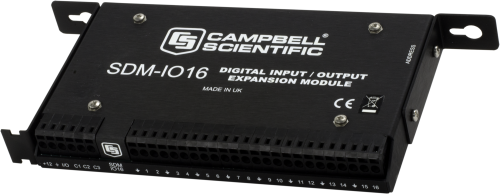
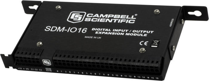
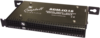
The SDM-IO16 expands the digital input and output channel count of Campbell Scientific data loggers.
Read MoreBenefits and Features
- Provides 16 digital I/O ports
- When configured as an input, each port can monitor logic state, count pulses, measure signal frequency, and determine duty cycle
Images
Detailed Description
The SDM-IO16 expands the digital input and/or output capability of Campbell Scientific data loggers. When a port is configured as an input, each port can monitor logic state, count pulses, measure signal frequency, and determine duty cycle. An option in the pulse counting mode enables switch debounce filtering, allowing the SDM-IO16 to accurately count switch closures. The SDM-IO16 can also be programmed to send an interrupt signal to the data logger when one or more input signals change state.
When configured as an output, each port can be set to 0 or 5 V by the data logger. A boost circuit allows an output that is set HI to source a current of up to 100 mA (at a reduced output voltage) for controlling external devices such as low voltage valves or relays.
Up to 15 SDM-IO16 modules can be addressed allowing up to 240 ports to be controlled by the data logger.
Data Logger Connection
The SDM Jumper Wire Kit (pn 32505) connects up to four SDMs to the data logger. This kit is recommended when multiple SDMs are connected to one data logger or for extremely short distances between the SDM and data logger. The CABLE5CBL-L cable is recommended for connecting a single SDM to the data logger, and for longer distances between the SDM and data logger.
Compatibility
Please note: The following shows notable compatibility information. It is not a comprehensive list of all compatible products.
Data Loggers
| Compatible | Note | |
|---|---|---|
| 21X (retired) | Output only | |
| CR10 (retired) | Output only | |
| CR1000 (retired) | ||
| CR1000X (retired) | ||
| CR1000Xe | ||
| CR10X (retired) | OS 1.17 or later | |
| CR200X (retired) | ||
| CR206X (retired) | ||
| CR23X (retired) | OS 1.14 or later | |
| CR295X (retired) | ||
| CR300 (retired) | ||
| CR3000 (retired) | For the CR3000, SDMs are connected to the ports labeled SDM-C1, SDM-C2, and SDM-C3. | |
| CR310 | ||
| CR500 (retired) | ||
| CR5000 (retired) | For the CR5000, SDMs are connected to the ports labeled SDM-C1, SDM-C2, and SDM-C3. | |
| CR510 (retired) | ||
| CR6 | ||
| CR800 (retired) | ||
| CR850 (retired) | ||
| CR9000 (retired) | ||
| CR9000X (retired) | ||
| GRANITE 9 |
Distributed Data Acquisition
| Compatible | Note | |
|---|---|---|
| GRANITE 10 | ||
| GRANITE 6 (retired) |
Additional Compatibility Information
Software Requirements
Support for all the functions requires CRBasic’s SDMIO16 instruction or Edlog’s Instruction 188. Instruction 188 is available in Edlog templates that post date March 2002. (LoggerNet version 2.1 contains this template.) Edlog templates that predate March 2002 can support only the output mode using Instruction 104. The SDMCD16AC instruction supports only the output mode in CRBasic.
Power Considerations
In input mode, the power consumption varies from 3 to 600 microamps depending on the mode and input frequencies. The data logger's rechargeable power supply can often power the SDM-IO16 in these pulse counting or status input applications.
However, when the SDM-IO16 is used in an output mode and is driving significant loads, an external power supply is recommended.
Enclosure Considerations
The SDM-IO16 requires a desiccated, non-condensing environment; a Campbell Scientific enclosure is recommended. An integral mounting bracket, grommets, and screws attach the SDM-IO16 to the backplate of a Campbell Scientific enclosure.
Sensor Cabling
This cabling is typically sold as a part of the sensors. If cabling is not provided, you can use our 9922 two-conductor cable (see Ordering Info). When the distance between the data logger and the SDM-IO16 are significant, verify that the sensor cable has adequate resistance/capacitance specifications. Also, avoid sensors with completion resistors in their pigtails; it's preferable to have the completion resistors at the data logger.
Specifications
| Function | Expands the digital input and/or output capability of a data logger. |
| Number of Channels | 16 |
| Operating Temperature | -25° to +50°C |
| SDM & I/O Port | 0/5 V logic level ports (for connecting to the datal ogger’s control/SDM ports) |
| EMC Status | Complies with EN 61326:1997. |
| Operating Voltage | 12 Vdc (nominal 9 to 18 V) |
| Minimum Frequency | 0 Hz is reported if there are less than two high-to-low signal transitions in the measurement interval. |
| Minimum Pulse Width | 244 μs |
| Default Switch Debounce Timing | Input and ground must remain closed for 3.17 ms then remain open for 3.17 ms to be counted as a closure. |
| Internal Clock Accuracy | ±0.01%, worst case (-25° to +50°C) |
| Maximum Pulse Measurement Interval | 15.9375 s |
| Dimensions | 23.0 x 10.0 x 2.4 cm (9 x 4 x 1 in.) |
| Weight | 350 g (12 oz) |
Maximum Frequency (with 50/50 duty cycle) |
|
| Switch Debounce-Mode Turned Off | 2.0 kHz on all channels simultaneously |
| Default Switch Debounce-Mode Enabled | 150 Hz on all channels |
Current Drain |
|
| -NOTE- | Current consumption is roughly proportional to input signal frequency and number of ports used. Current drawn from any output must be added to the quiescent level to obtain the total current drain. |
| Typical Standby | 600 µA (all ports high, no load, excludes pulse counting) |
| Maximum | 3 µA (active with all 16 ports counting pulses at 2 kHz and no output load) |
Output |
|
| ON/HI Voltage (no load) |
|
| OFF/LO Voltage (no load) |
|
| Sink Current | Output will sink 8.6 mA from a 5 V source. |
| Source Current |
|
Input |
|
| Voltage |
|
| Protection | Input clamped at -0.6 V and ±5.6 V relative to ground (via a 33 Ω resistor to withstand a continuous current flow of 200 mA) |
| Source Current |
|
| Impedance | Biased to +5 V relative to ground (by a 100 kohm resistor) |
Related Documents
Product Brochures
FAQs for
Number of FAQs related to SDM-IO16: 1
-
Both of these are SDM devices. Each SDM device that is connected to a data logger needs a different SDM address (that is, 0 through 15). All SDM devices connect to the CR1000’s 12V, G, C1, C2, or C3 terminals. Up to 15 SDM devices can be connected to one data logger.
For more information, see the Synchronous Devices for Measurement (SDMs) page.