
Adds data link possibilities among data loggers, PCs, and sensors


Overview
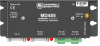
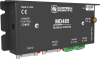
The MD485 is an intelligent RS-485 interface that permits a PC to address and communicate with one or more data loggers over a distance of up to 1200 m. This interface also supports data-logger-to-data-logger communication, callback from a remote data logger, PC-to-printer communications, and digital camera-to-data-logger connections.
Read MoreBenefits and Features
- Compatible with most Campbell Scientific data loggers
- Can be used with a phone modem, Ethernet link, or spread spectrum radio to extend the distance between the data logger and PC
- Increases the distance allowed between a CC5MPX digital camera and a PakBus data logger
- Extends the distance between AVW200 Vibrating-Wire Interfaces for situations where wireless communication is impractical
- Internal buffering ensures that data is not lost during transmission and allows each side to operate at different baud rates
- Includes gas tubes on the RS-485 ports and a ground lug for better surge protection
- Communicates at rates up to 115.2 kbps
Images


Detailed Description
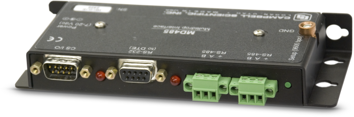
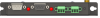
The MD485 includes three ports (RS-232, CS I/O, RS-485) for connecting a PC, a data logger, or another MD485. Any two ports can be used at a time.
The MD485 can be configured to provide transparent communications, MD9 emulation, and PakBus networking. Although the MD485 can emulate an MD9, the MD485 can not be added to an existing MD9 network. PakBus networking requires the data loggers to use the PakBus communications protocol. PC400 or LoggerNet software is used to initiate and control the communications link.
Required Equipment
The MD485 is shipped with the 10873 cable and SC12 cable for connecting it to a PC or data logger. Point-to-point and point-to-multipoint networks use the following equipment:
- PC running PC400 or LoggerNet software
- At the computer site, an MD485 is connected to the computer via a pn 10873 cable.
- At each data logger site, an MD485 is connected either to the data logger’s CS I/O port (not compatible with the CR200(X)-series) or the data logger’s RS-232 port (not compatible with the CR510 or CR10X). The SC12 serial cable connects an MD485 modem to the CS I/O port. The pn 18663 9-pin pin (male) to 9-pin pin (male) null modem cable connects the MD485 to the RS-232 port.
- The CABLE2TP-L Two-Twisted-Pair 22-AWG Cable connects an MD485 to another MD485. Please note that when communicating at maximum distances and high data rates, a cable with polyethylene insulation is recommended.
- CR200(X)-series, CR510, CR800, CR850, CR10X, CR1000, or CR3000 datalogger.
- Power supply
- Environmental enclosure. At each field site, the data logger, power supply, and MD485 should be housed in the enclosure if the equipment is not located in a building.
Powering the MD485
AC power is typically used at the computer site; a pn 15966 wall charger is required. At the field site, the MD485 is powered by the data logger through its CS I/O port. If the MD485 is connected to the data logger’s RS-232 port instead of the CS I/O port, or if the data logger was purchased before 12/97, a pn 14291 Field Power Cable is required. Phone-to-MD485 and spread spectrum radio-to-MD485 networks also require a power supply with a null modem port . An A100 adapter used with a PS150 or PS200 power supply provides this capability. The PS150 or PS200 is recharged via a wall charger or a solar panel.
Compatibility
Please note: The following shows notable compatibility information. It is not a comprehensive list of all compatible products.
Data Loggers
| Compatible | Note | |
|---|---|---|
| 21X (retired) | ||
| CR10 (retired) | ||
| CR1000 (retired) | ||
| CR10X (retired) | ||
| CR200X (retired) | ||
| CR206X (retired) | ||
| CR23X (retired) | ||
| CR295X (retired) | ||
| CR300 (retired) | Use a 18663 null modem cable. | |
| CR3000 (retired) | ||
| CR350 | Use a 18663 null modem cable. | |
| CR500 (retired) | ||
| CR5000 (retired) | ||
| CR510 (retired) | ||
| CR6 | The CR6 has integrated RS-485. | |
| CR800 (retired) | ||
| CR850 (retired) | ||
| CR9000 (retired) | ||
| CR9000X (retired) |
Additional Compatibility Information
Enclosure Considerations
A desiccated, non-condensing environment is required. The MD485 includes built-in keyhole flanges for mounting to the backplate of a Campbell Scientific enclosure.
Combining with Other Devices
The MD485 can be combined with our AVW200-series Vibrating Wire Interfaces, CC640 Digital Camera, Ethernet links, phone modems (including cellular), and spread spectrum radios. Field site equipment should be housed in an environmental enclosure. Information about configuring the other devices is provided in the user manuals.
Power Considerations
AC power is typically used at the computer site; a pn 15966 wall charger is required. At the field site, the MD485 is powered by the data logger through its CS I/O port. If the MD485 is connected to the data logger’s RS-232 port instead of the CS I/O port, or if the data logger was purchased before 12/97, a pn 14291 Field Power Cable is required. Phone-to-MD485 and spread spectrum radio-to-MD485 networks also require a power supply with a null modem port. An A100 adapter used with a PS150 or PS200 power supply provides this capability. The PS150 or PS200 is recharged via a wall charger or a solar panel.
Specifications
| Function | Permits a PC to address and communicate with one or more data loggers over a distance of up to 1,200 m. |
| Transmission Distance or Area | 1,219 m (4,000 ft) Can increase distance by using more MD485s or combining with spread-spectrum radios, Ethernet, or phone. |
| Baud Rates | 1200, 9600, 19.2k, 38.4k, 57.6k, 115.2k bps |
| Voltage | 12 Vdc (from data logger or pn 15966 wall charger) |
| Surge | Complies with IEC61000-4-5, test level 3 (±2 kV, 2 Ω coupling impedance) |
| Operating Temperature |
|
| Service Requirements | CABLE2TP two-twisted pair cables must be installed between networked data loggers and base. |
| Maximum Cable Length | 1,219 m (4,000 ft) |
| Dimensions | 15.88 x 6.35 x 1.91 cm (6.25 x 2.5 x 0.75 in.) |
| Weight | 127.6 g (4.5 oz) |
Current Drain |
|
| Standby Mode | 1.2 mA |
| Communicating | 2 to 7 mA |
Power |
|
| Standby Mode | 14.4 mW |
| Communicating | 24 to 84 mW |
ESD |
|
| Air Discharge | Complies with IEC61000-4-2, test level 4 (±15 kV) |
| Contact Discharge | Complies with IEC61000-4-2, test level 4 (±8 kV) |
Related Documents
Product Brochures
Manuals
Compliance
Downloads
MD485 OS v.05 (583 KB) 06-04-2012
Current MD485 operating system. Requires the Device Configuration Utility.
Device Configuration Utility v.2.35.02 (49.5 MB) 22-06-2026
A software utility used to download operating systems and set up Campbell Scientific hardware. Also will update PakBus Graph and the Network Planner if they have been installed previously by another Campbell Scientific software package.
Supported Operating Systems:
Windows 11 or 10 (Both 32 and 64 bit)
Listed Under
FAQs for
Number of FAQs related to MD485: 13
Expand AllCollapse All
-
No. Isolation circuitry is not always needed, and it presents a significant increase in power consumption for battery-operated stations. For situations where external isolation modules are required, external isolation modules can be added between stations.
-
No. The MD485 is configured to be a serial converter between two of the interfaces. The MD485 serves to convert CS I/O to RS-485, RS-232 to RS-485, or CS I/O to RS-232.
-
256 MD485 devices can exist on a single bus. The MD485 presents ⅛ of a unit load (electrical impedance load) to the network. An RS-485 network should not exceed 32 unit loads: 256 ∙ ⅛ = 32.
-
RS-485 networks should follow a bus topology whenever possible (devices daisy-chained in a linear fashion). The total amount of cable used in a single network should not exceed 1,200 m. An RS-485 repeater or a data logger with multiple MD485 devices can be used to extend the length of a network or to create more complex network topologies.
-
No. The device can also be connected directly to other devices such as a computer, radio, cellular modem, serial server, or other vendor RTU. When it is not connected to a data logger, the MD485 is most commonly used to create a multidrop network behind another communications peripheral or off a computer’s serial port.
-
No. The RS-485 data transceivers used in the MD485 feature fail-safe circuitry, which guarantees a logic-high receiver output when the receiver inputs are open or shorted. Because of this, biasing resistors are not needed. The transceivers also feature reduced slew-rate drivers that minimize electromagnetic interference (EMI) and reduce reflections. Because of this, termination resistors do not need to be used for most applications.
-
Typically, only one MD485 is connected to a data logger. Sometimes two are connected to create different network segments. Technically, however, one MD485 can be connected to each data logger serial port, and up to five MD485 devices can be connected to a single data logger CS I/O port.
-
The MD485 is compatible with nearly any serial line communications protocol. Most notably, the MD485 is regularly used for PakBus, Modbus RTU, Modbus ASCII, and DNP3.
-
Absolutely. The RS-485 interface of the MD485 meets the EIA/TIA-485 standards for half-duplex communications. Campbell Scientific customers have used the MD485 in conjunction with many other off-the-shelf RS-485 interfaces.
-
The MD485 provides enhanced performance when using PakBus communications. Additionally, the MD485 consumes very little power when idle, making it ideal for remote battery-powered installations. The MD485 also provides excellent surge/ESD (electrostatic discharge) protection and an integrated CS I/O port for plug-and-play operation with Campbell Scientific data loggers.