This product has limited availability. Some accessories, replacement parts, or services may still be available when it is no longer available.
Signal Noise
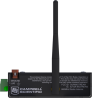
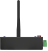
Includes built-in radio


Overview
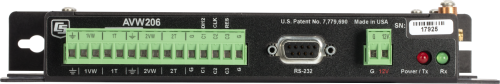
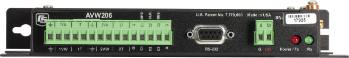
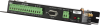
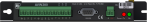
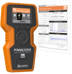
The AVW206 is a vibrating wire analyzer module that includes an internal 910 to 918 MHz spread-spectrum radio for wireless communication, typically used in the U.S. and Canada. With this vibrating wire analyzer module, your data logger can measure vibrating wire strain gages, pressure transducers, piezometers, tiltmeters, crackmeters, and load cells. These sensors are used in a wide variety of structural, hydrological, and geotechnical applications because of their stability, accuracy, and durability.
Read MoreBenefits and Features
- Provides better measurements by significantly reducing incorrect readings caused by noise sources
- Interfaces two vibrating wire sensors; more sensors may be connected if an AM16/32B multiplexer is used
- Self-checking diagnostics give continual feedback on sensor condition
- High resolution—less than 0.001 Hz (industry standard is 0.1 Hz)
- Low current drain
- Remote, wireless operation with on-board radio
- Interfaces both temperature and frequency measurements from vibrating wire sensors
Images


Detailed Description
The AVW206 uses vibrating wire spectral-analysis technology (VSPECT™). VSPECT observes the incoming sensor signal, performs a Fourier transform and a spectral analysis (transforming the time series into individual sinusoidal components in the frequency spectrum), and determines the sensor frequency by identifying the largest signal in the acceptable range while filtering out environmental and electrical noise.
The AVW206 analyzer module also provides many self-checking diagnostics such as vibrating element signal strength, signal-to-noise ratio, vibrating element signal decay ratio, and incorrect signal response. These diagnostics can be running in the background to give continual feedback of the condition for each sensor.
The AVW206 typically transmits its data to an RF401(A) spread-spectrum radio that is connected to the data logger. The AVW206 can also be connected directly to the data logger.
Compatibility
Please note: The following shows notable compatibility information. It is not a comprehensive list of all compatible products.
Data Loggers
| Compatible | Note | |
|---|---|---|
| 21X (retired) | ||
| CR10 (retired) | The CR10 supports the SDI-12 mode only. | |
| CR1000 (retired) | ||
| CR1000X (retired) | ||
| CR1000Xe | ||
| CR10X (retired) | The CR10X supports the SDI-12 mode only. | |
| CR200X (retired) | ||
| CR206X (retired) | ||
| CR23X (retired) | The CR23X supports the SDI-12 mode only. | |
| CR295X (retired) | ||
| CR300 (retired) | ||
| CR3000 (retired) | ||
| CR310 | ||
| CR350 | ||
| CR500 (retired) | ||
| CR5000 (retired) | The CR5000 supports the SDI-12 mode only. | |
| CR510 (retired) | ||
| CR800 (retired) | ||
| CR850 (retired) | ||
| CR9000 (retired) | ||
| CR9000X (retired) |
Mounting Equipment
| Compatible | Note | |
|---|---|---|
| ENC10/12 | If using the RS-232 port, the AVW206 must be mounted flat to fit in an ENC10/12. | |
| ENC12/14 | If using the RS-232 port, the AVW206 must be mounted flat to fit in an ENC12/14. | |
| ENC14/16 | ||
| ENC16/18 | ||
| ENC24/30 |
Additional Compatibility Information
Sensors
The AVW206 Vibrating Wire Spectrum Analyzer Module allows our data loggers to measure vibrating wire strain gages, pressure transducers, piezometers, tiltmeters, crackmeters, and load cells.
Communications
The AVW206's internal spread spectrum radio can transmit data to an RF401A, RF401, or RF430. The AVW206 does not have a transparent mode, and therefore its internal radio cannot communicate with an RF400 radio.
Enclosure Considerations
The AVW206 requires a desiccated, non-condensing environment. A Campbell Scientific enclosure is recommended when the analyzer module is in the field. The AVW206 has built-in keyhole flanges for mounting to an enclosure backplate.
Power Considerations
The AVW206 is typically powered by the data logger's power supply.
Operating System Considerations
Newer modules with 250 mW radios must use OS 5 or higher for their operating system.
Specifications
| -NOTE- | Electrical specifications are valid over a -25° to +50°C range unless otherwise specified. Non-condensing environment required. |
| Internal Radio Frequency Range | 910 to 918 MHz |
| Radio Power |
250 mW Older AVW206 modules (serial # < 11224) have 100 mW radios. |
| Number of Vibrating Wire Sensors Measured | Up to 2 vibrating wire sensors can be connected to the analyzer module. Additional sensors can be measured by using an AM16/32-series multiplexer. |
| Power Requirements | 9.6 to 16 Vdc |
| Analog Input/Outputs | 2 differential (DF) vibrating wire measurements (V+ and V-) and 2 single-ended (SE) ratiometric resistive half-bridge measurements (T+ and T-) for vibrating wire sensor's onboard temperature sensor. |
| Digital Control Ports |
3 digital control ports (C1 – C3)
|
| RS-232 Port | 1 9-pin RS-232 port (for connecting to a data logger COM port) |
| Measurement Resolution | 0.001 Hz RMS (±250 mV differential input range; -55° to +85°C) |
| Measurement Accuracy | ±0.013% of reading (±250 mV differential input range; -55° to +85°C) |
| Input Voltage Range | ±250 mV (differential) for vibrating wire inputs |
| Common Mode Range | ±25 V |
| Baud Rates | Selectable from 1200 to 38.4 kbps (ASCII protocol is one start bit, one stop bit, eight data bits, and no parity.) |
| Memory |
|
| CE Compliance Standards to which Conformity Is Declared | IEC61326:2002 |
| Dimensions | 21.6 x 11.18 x 3.18 cm (8.5 x 4.5 x 1.2 in.) |
| Weight | 0.43 kg (0.95 lb) |
Typical Current Drain @ 12 Vdc |
|
| Quiescent, Radio Off | ~0.3 mA |
| Radio Duty Cycling 1 s | ~3 mA (includes quiescent current) |
| Radio Always On | ~26 mA (radio transmit current 100 mA) |
| Active RS-232 Communication | ~6 mA (3 s after communication stops, the current will drop to the quiescent current.) |
| Measurement | ~25 mA (averaged over the 2 s) |
Related Documents
Videos & Tutorials

Downloads
AVW200 OS v.06 (551 KB) 10-06-2016
Current AVW200 firmware. Use the Device Configuration Utility version 1.13 or greater to send firmware and to configure the AVW200.
FAQs for
Number of FAQs related to AVW206: 14
Expand AllCollapse All
-
No. An AVW206, AVW211, or AVW216 is not capable of communicating with other AVW200-series modules.
-
-
The recommended maximum is 24 AVW206 devices.
-
Here is an example of the code that can be added to a data logger program to acquire both the voltage of the AVW206 and the radio signal strength:
AVW200 (VW_Meas_Result,ComSDC7,0,200,VWData(1),1,1,1,450,6000,1,_60Hz,1,0)
GetVariables (AVW206_Batt_Result,ComSDC7,0,200,0000,0,"status","BattVoltage",RemoteBatt,1)
GetVariables (AVW206_Sig_Result,ComSDC7,0,200,0000,0,"Status","RfSignalLevel",SignalStrength,1)
-
The AVW200-series modules are not required, but they do reduce the chance of erroneous readings by filtering electrical noise that is sometimes present.
-
The AVW200 must be wired directly to the data logger via a cable.
The AVW206, AVW2011, and AVW216 have built-in spread-spectrum radios tuned to different frequencies that allow the data logger to communicate with a remote AVW device through an appropriate radio link.
-
It takes 2 s for the AVW200-series modules to acquire a measurement from each sensor. An AVW200-series module servicing two AM16/32B multiplexers, each with 16 vibrating wire sensors, requires approximately 64 s to acquire data.
-
Two probable causes are the following:
- The SerialOpen() instruction has not been added to the data logger code.
- The correct PakBus address setting has not been used in the AVW200 instruction.
-
Use pn 17855, Data Cable, RS-232 Male to Pigtail.