Tips to Troubleshoot and Optimize Large RF Networks: Part 3
by Nathanael Wright | Updated: 01/02/2024 | Comments: 0
Blog Topics
Area / Application


Product Category


Corporate / News
Search the Blog
Blog Languages
Subscribe to the Blog
Get an email when a new article is posted. Choose the topics that interest you most.
Suggest an Article
Is there a topic you would like to learn more about? Let us know.
Here is our final blog article in our three-part series on troubleshooting your radio frequency (RF) networks. In this article, I’ll share with you four more tips (11 through 14). If you missed parts 1 and 2 or want to review them again, here are the links:
- Tips to Troubleshoot and Optimize Large RF Networks: Part 1
- Tips to Troubleshoot and Optimize Large RF Networks: Part 2
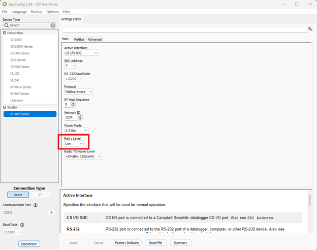
Tip #11 - Reduce retries (RF407-series and RF401/A only).
In large networks where interference or packet loss is high, keep the default Retry Level set to Low within the Device Configuration Utility. That reduces retries on the network from interfering with other device communications attempts.
| Retry Level | Retry Count |
|---|---|
| None | 0 |
| Low | 2 |
| Medium | 4 |
| High | 6 |
Tip #12 - Avoid interference from other radios.
If your radios regularly disconnect from one another and connectivity seems unstable, other spread-spectrum radio interference may be present. Reducing the Frequency Range that your radios communicate over may help.
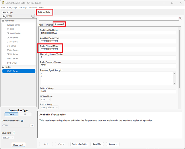
Reduce the frequency range of RF407-series radios.
On the RF407, the frequency is reduced in the Device Configuration Utility > Settings Editor > Advanced > Radio Channel Mask.
All devices in the RF407-series radio network must use an identical set of active channels. The 16-digit Hex Radio Channel Mask correlates to the 64 segments of the radio frequency band. Each of the 16 hex values represents four binary values. The lowest frequencies in the band begin on the left, and the highest are on the right. Turn off the groups of four by setting the F to 0. Simply setting the 0 back to an F turns the group back on. See the following table for more granular frequency toggling.
| Hex Value | Effect | Hex Value | Effect |
|---|---|---|---|
| 0 | Turns all four channels off | A | Turns on channels 2 and 4 |
| 1 | Turns on channel 1 | B | Turns on channels 1, 2, and 4 |
| 2 | Turns on channel 2 | C | Turns on channels 3 and 4 |
| 3 | Turns on channels 1 and 2 | D | Turns on channels 1, 3, and 4 |
| 4 | Turns on channel 3 | E | Turns on channels 2, 3, and 4 |
| 5 | Turns on channels 1 and 3 | F | Turns on all four channels |
| 6 | Turns on channels 2 and 3 | ||
| 7 | Turns on channels 1, 2, and 3 | ||
| 8 | Turns on channel 4 | ||
| 9 | Turns on channels 1 and 4 |
The following table shows the bit-by-bit frequency breakdown. The first four bits correlate to the first hexadecimal value. The second four bits correlate to the second hexadecimal value, and so on.
| Freq (MHz) | Freq (MHz) | Freq (MHz) | Freq (MHz) | ||||
|---|---|---|---|---|---|---|---|
| Bit 0 | 902.4 | Bit 16 | 908.8 | Bit 32 | 915.2 | Bit 48 | 921.6 |
| Bit 1 | 902.8 | Bit 17 | 909.2 | Bit 33 | 915.6 | Bit 49 | 922 |
| Bit 2 | 903.2 | Bit 18 | 909.6 | Bit 34 | 916 | Bit 50 | 922.4 |
| Bit 3 | 903.6 | Bit 19 | 910 | Bit 35 | 916.4 | Bit 51 | 922.8 |
| Bit 4 | 904 | Bit 20 | 910.4 | Bit 36 | 916.8 | Bit 52 | 923.2 |
| Bit 5 | 904.4 | Bit 21 | 910.8 | Bit 37 | 917.2 | Bit 53 | 923.6 |
| Bit 6 | 904.8 | Bit 22 | 911.2 | Bit 38 | 917.6 | Bit 54 | 924 |
| Bit 7 | 905.2 | Bit 23 | 911.6 | Bit 39 | 918 | Bit 55 | 924.4 |
| Bit 8 | 905.6 | Bit 24 | 912 | Bit 40 | 918.4 | Bit 56 | 924.8 |
| Bit 9 | 906 | Bit 25 | 912.4 | Bit 41 | 918.8 | Bit 57 | 925.2 |
| Bit 10 | 906.4 | Bit 26 | 912.8 | Bit 42 | 919.2 | Bit 58 | 925.6 |
| Bit 11 | 906.8 | Bit 27 | 913.2 | Bit 43 | 919.6 | Bit 59 | 926 |
| Bit 12 | 907.2 | Bit 28 | 913.6 | Bit 44 | 920 | Bit 60 | 926.4 |
| Bit 13 | 907.6 | Bit 29 | 914 | Bit 45 | 920.4 | Bit 61 | 926.8 |
| Bit 14 | 908 | Bit 30 | 914.4 | Bit 46 | 920.8 | Bit 62 | 927.2 |
| Bit 15 | 908.4 | Bit 31 | 914.8 | Bit 47 | 921.2 | Bit 63 | 927.6 |
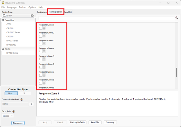
Reduce the frequency range of RF450, RF451, and RF452 radios.
On the RF450/451/452, the radio frequency range is reduced in the Device Configuration Utility from the Settings Editor tab. Scroll down to the Frequency Zones. Zones can be toggled off by setting the value for the zone to 0. Changing the value back to 1 re-enables the zone. Clicking in the zone field displays the relevant frequency in the information section at the bottom of your Device Configuration Utility window.
Tip #13 - Consider the base antenna siting.
If you experience frequent disconnects, it may be useful to check the location and position of the base station antenna. It could be problematic if it is mounted to a tower where it is close to other antennas. If possible, look for another antenna mounting location.
The 21107 Radio Test Kit from Campbell Scientific allows you to set up a temporary base station on a tripod and a remote radio station and then move them to find the most suitable location for a tower or station. Verifying that the radio equipment being deployed is a good fit for the location is especially useful during the early phase of a project.
Tip #14 - Use a cavity band-pass filter.
Use a cavity band-pass filter on your base station radio if the signal consistently goes out during certain times of the day. Install a signal filter to the connection going from the antenna into the data logger. Ensure that the filter is in the range of the radio, generally 902 to 928 MHz.
A final word
I hope you found the 14 tips shared in this three-part series helpful. While this concludes our series, you can review all the steps by reading our Troubleshooting tips: Large radio networks white paper. If you have any questions or comments, please post them below.


About the Author
 Nathanael Wright is a Technical Support Specialist at Campbell Scientific, Inc. He provides technical support for data loggers, instruments, and communications equipment. Nathanael has a bachelor's degrees in Computer Information Science and Business Administration, and an MBA. In addition, Nathanael has more than 15 years of experience working in IP communications. Away from work, he enjoys breakdancing, hiking, writing, publishing books, and fiddling with computer equipment.
Comments
Please log in or register to comment.