HFP01-L Soil Heat Flux Plate
Extreme Accuracy
Ideal for energy-balance and Bowen-ratio systems
weather applications supported water applications supported energy applications supported gas flux and turbulence applications supported infrastructure applications supported soil applications supported

Overview

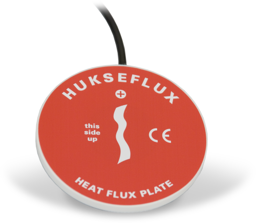
The HFP01, manufactured by Hukseflux, measures soil heat flux, typically for energy-balance or Bowen-ratio flux systems. It outputs a voltage signal that is proportional to the heat flux of the surrounding medium. At least two sensors are required for each site to provide spatial averaging. Sites with heterogeneous media may require additional sensors.

Read More

Benefits and Features

  • Compatible with most Campbell Scientific dataloggers
  • Compatible with the CWS900-series interfaces, allowing it to be used in a wireless sensor network

Images


Detailed Description

The HFP01 uses a thermopile to measure temperature gradients across its plate. Operating in a completely passive way, it generates a small output voltage that is proportional to this differential temperature. Assuming that the heat flux is steady, that the thermal conductivity of the body is constant, and that the sensor has negligible influence on the thermal flow pattern, the signal of the HFP01 is directly proportional to the local heat flux.

The HFP01’s output is in millivolts. To convert this measured voltage to heat flux, it must be divided by the plate’s calibration constant. A unique calibration constant is supplied with each sensor.

Note: In an energy-balance installation, all sensors must be completely inserted into the soil face before the hole is backfilled.

Specifications

Sensor Type Thermopile
Sensitivity 50 μV W-1 m-2 (nominal)
Nominal Resistance 2 Ω
Temperature Range -30° to +70°C
Sensor Thermal Resistance < 6.25 x 10⁻³ K m2 W-1
Measurement Range ±2000 W m-2
Expected Typical Accuracy Within -15% to +5% in most common soils (12 hour totals)
Plate Diameter 80 mm (3.15 in.)
Plate Thickness 5 mm (0.20 in.)
Weight 200 g (7.05 oz) without cable

Compatibility

Please note: The following shows notable compatibility information. It is not a comprehensive list of all compatible products.

Data Loggers

Compatible Note
CR1000 (retired)
CR1000X
CR300
CR3000 (retired)
CR310
CR350
CR6
CR800 (retired)
CR850 (retired)

FAQs for

Number of FAQs related to HFP01-L: 10

Expand AllCollapse All

  1. It depends on the sign convention used to describe heat flux through the wall. Heat flux that enters the red face and exits the blue face of the HFP01-L results in a positive analog output or positive heat. If the plate is already installed and it is desirable to use the opposite sign convention, change the sign of the multiplier to make it a negative value.

  2. Yes, however, care must be taken to ensure a water-tight splice, such as by using an adhesive-lined heat shrink to cover the splice. This is important because splicing cable together increases the likelihood that water may enter the cable and cause shorting, corrosion, and some other potential issues, which can cause measurement issues.

    Because of the potential issues, do not splice any sensor cable without first contacting Campbell Scientific to discuss the sensor in detail.

  3. The information included on a calibration sheet differs with each sensor. For some sensors, the sheet contains coefficients necessary to program a data logger. For other sensors, the calibration sheet is a pass/fail report.

  4. Most Campbell Scientific sensors are available as an –L, which indicates a user-specified cable length. If a sensor is listed as an –LX model (where “X” is some other character), that sensor’s cable has a user-specified length, but it terminates with a specific connector for a unique system:

    • An –LC model has a user-specified cable length for connection to an ET107, CS110, or retired Metdata1.
    • An –LQ model has a user-specified cable length for connection to a RAWS-P weather station.

    If a sensor does not have an –L or other –LX designation after the main model number, the sensor has a set cable length. The cable length is listed at the end of the Description field in the product’s Ordering information. For example, the 034B-ET model has a description of “Met One Wind Set for ET Station, 67 inch Cable.” Products with a set cable length terminate, as a default, with pigtails.

    If a cable terminates with a special connector for a unique system, the end of the model number designates which system. For example, the 034B-ET model designates the sensor as a 034B for an ET107 system.

    • –ET models terminate with the connector for an ET107 weather station.
    • –ETM models terminate with the connector for an ET107 weather station, but they also include a special system mounting, which is often convenient when purchasing a replacement part.
    • –QD models terminate with the connector for a RAWS-F Quick Deployment Station.
    • –PW models terminate with the connector for a PWENC or pre-wired system.
  5. Not every sensor has different cable termination options. The options available for a particular sensor can be checked by looking in two places in the Ordering information area of the sensor product page:

    • Model number
    • Cable Termination Options list

    If a sensor is offered in an –ET, –ETM, –LC, –LQ, or –QD version, that option’s availability is reflected in the sensor model number. For example, the 034B is offered as the 034B-ET, 034B-ETM, 034B-LC, 034B-LQ, and 034B-QD.

    All of the other cable termination options, if available, are listed on the Ordering information area of the sensor product page under “Cable Termination Options.” For example, the 034B-L Wind Set is offered with the –CWS, –PT, and –PW options, as shown in the Ordering information area of the 034B-L product page.

    Note: As newer products are added to our inventory, typically, we will list multiple cable termination options under a single sensor model rather than creating multiple model numbers. For example, the HC2S3-L has a –C cable termination option for connecting it to a CS110 instead of offering an HC2S3-LC model. 

  6. The HFP01-L uses a thermopile to measure flux across the plate. The output of a thermopile is proportional to the temperature gradient across the thermopile. The HFP01-L nominal calibration is 20 W m-2 /mV. The HFP01-L output voltage will depend on the temperature gradient (flux) across the plate.

  7. This depends on the information contained in the calibration sheet:

    • If the calibration sheet contains coefficient information, Campbell Scientific keeps a copy, and a replacement copy can be requested.
    • If the calibration sheet does not contain coefficients, Campbell Scientific does not keep a copy. It may be possible to contact the original manufacturer for a replacement copy.
  8. Because of the loss of IR radiation, nearly all thermopile instruments typically have a negative offset. This offset is most easily visible at night-time, when a small negative value is read instead of zero. This same offset is present during the daytime, but it is not as visible because of the large solar signal.

    Another common issue involves leveling an instrument. Leveling a thermopile instrument can cause errors in the direct beam component because the cosine response is not correct. These errors are more notable when the sun is close to the horizon because the angle is so shallow.

  9. Many Campbell Scientific sensors are available with different cable termination options. These options include the following:

    • The –PT (–PT w/Tinned Wires) option is the default option and does not display on the product line as the other options do. The cable terminates in pigtails that connect directly to a data logger.
    • In the –C (–C w/ET/CS110 Connector) option, the cable terminates in a connector that attaches to a CS110 Electric Field Meter or an ET-series weather station.
    • In the –CWS (–CWS w/CWS900 Connector) option, the cable terminates in a connector that attaches to a CWS900-series interface. Connection to a CWS900-series interface allows the sensor to be used in a wireless sensor network.
    • In the –PW (–PW w/Pre-Wire Connector) option, the cable terminates in a connector that attaches to a prewired enclosure.
    • In the –RQ (–RQ w/RAWS Connector) option, the cable terminates in a connector that attaches to a RAWS-P Permanent Remote Automated Weather Station.

    Note: The availability of cable termination options varies by sensor. For example, sensors may have none, two, or several options to choose from. If a desired option is not listed for a specific sensor, contact Campbell Scientific for assistance.

  10. To incorporate a sensor that is compatible with wireless sensor interfaces into a wireless network, a CWS900-series wireless sensor interface is needed, as well as an A205 CWS-to-PC interface to configure it.