024A Wind Direction Sensor
Reliable, Accurate Wind Direction
Compatible with most Campbell Scientific data loggers
weather applications supported water applications supported energy applications supported gas flux and turbulence applications supported infrastructure applications supported soil applications supported

Overview

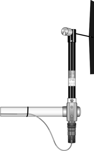
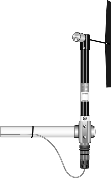
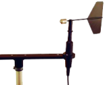
The 024A, manufactured by Met One, is a wind vane that measures wind direction only. You can use it in tandem with the 014A Wind Speed Sensor; however, this combination has been largely replaced by the 034B, which monitors both wind speed and wind direction.

Read More

Images


Detailed Description

The 024A Wind Vane measures wind direction from 0 to 360 degrees with a 5 degree accuracy specification. Wind direction is sensed with a 10 kohm potentiometer. With the precision excitation voltage from the data logger applied to the potentiometer element, the output signal is an analog voltage that is directly proportional to the azimuth of the wind direction.

Specifications

Sensor Vane
Measurement Description Wind direction
Operating Range 0 to 360°
Threshold 0.45 m s-1 (1.0 mph)
Accuracy ±5°
Operating Temperature Range -50° to +70°C (assumes non-riming conditions)
Delay Distance < 1.5 m (5 ft)
Damping Ratio
  • 0.25 (standard)
  • 0.4 (optional fast response)
Resolution 0.5°
Height 33.8 cm (13.3 in.)
Length 44.7 cm (17.6 in.)
Vane Height 30.5 cm (12 in.)
Vane Width 7.6 cm (3 in.)
Weight 450 g (1 lb)

Potentiometer

Sand, Dust, and Fungus MIL-E-5272
Salt Spray MIL-E-12934
Resistance 0 to 10 kΩ

Compatibility

Please note: The following shows notable compatibility information. It is not a comprehensive list of all compatible products.

Data Loggers

Compatible Note
CR1000 (retired)
CR1000X
CR300
CR3000 (retired)
CR310
CR350
CR6
CR800 (retired)
CR850 (retired)

Additional Compatibility Information

Mounting

The 024A can be attached to a crossarm via a 17953 NU-RAIL fitting or a CM220 Right Angle Mounting Bracket. Alternatively, the 024A can be attached to the top of a CM106B or a stainless-steel tripod via the CM216 Sensor Mounting Kit. The CM216 extends 4 in. above the mast of the tripod.

Data Logger Considerations

The 024A uses one single-ended input channel on the data logger. An excitation channel is required but due to the high impedance of the 024A, can be shared with other high impedance sensors.

Programming

The 024A is read by the BrHalf instruction in CRBasic and by Instruction 4 (Excite-Delay-Single-ended Measurement) in Edlog.


FAQs for

Number of FAQs related to 024A: 4

Expand AllCollapse All

  1. Most Campbell Scientific sensors are available as an –L, which indicates a user-specified cable length. If a sensor is listed as an –LX model (where “X” is some other character), that sensor’s cable has a user-specified length, but it terminates with a specific connector for a unique system:

    • An –LC model has a user-specified cable length for connection to an ET107, CS110, or retired Metdata1.
    • An –LQ model has a user-specified cable length for connection to a RAWS-P weather station.

    If a sensor does not have an –L or other –LX designation after the main model number, the sensor has a set cable length. The cable length is listed at the end of the Description field in the product’s Ordering information. For example, the 034B-ET model has a description of “Met One Wind Set for ET Station, 67 inch Cable.” Products with a set cable length terminate, as a default, with pigtails.

    If a cable terminates with a special connector for a unique system, the end of the model number designates which system. For example, the 034B-ET model designates the sensor as a 034B for an ET107 system.

    • –ET models terminate with the connector for an ET107 weather station.
    • –ETM models terminate with the connector for an ET107 weather station, but they also include a special system mounting, which is often convenient when purchasing a replacement part.
    • –QD models terminate with the connector for a RAWS-F Quick Deployment Station.
    • –PW models terminate with the connector for a PWENC or pre-wired system.
  2. Not every sensor has different cable termination options. The options available for a particular sensor can be checked by looking in two places in the Ordering information area of the sensor product page:

    • Model number
    • Cable Termination Options list

    If a sensor is offered in an –ET, –ETM, –LC, –LQ, or –QD version, that option’s availability is reflected in the sensor model number. For example, the 034B is offered as the 034B-ET, 034B-ETM, 034B-LC, 034B-LQ, and 034B-QD.

    All of the other cable termination options, if available, are listed on the Ordering information area of the sensor product page under “Cable Termination Options.” For example, the 034B-L Wind Set is offered with the –CWS, –PT, and –PW options, as shown in the Ordering information area of the 034B-L product page.

    Note: As newer products are added to our inventory, typically, we will list multiple cable termination options under a single sensor model rather than creating multiple model numbers. For example, the HC2S3-L has a –C cable termination option for connecting it to a CS110 instead of offering an HC2S3-LC model. 

    1. Using Short Cut, click the applicable wind direction sensor in the Selected Sensors list of the Outputs screen.
    2. The two output options enabled are Sample and WindVector. Select WindVector.
    3. The WindVector instruction has output options. Select an option with mean wind direction in it.
  3. Many Campbell Scientific sensors are available with different cable termination options. These options include the following:

    • The –PT (–PT w/Tinned Wires) option is the default option and does not display on the product line as the other options do. The cable terminates in pigtails that connect directly to a data logger.
    • In the –C (–C w/ET/CS110 Connector) option, the cable terminates in a connector that attaches to a CS110 Electric Field Meter or an ET-series weather station.
    • In the –CWS (–CWS w/CWS900 Connector) option, the cable terminates in a connector that attaches to a CWS900-series interface. Connection to a CWS900-series interface allows the sensor to be used in a wireless sensor network.
    • In the –PW (–PW w/Pre-Wire Connector) option, the cable terminates in a connector that attaches to a prewired enclosure.
    • In the –RQ (–RQ w/RAWS Connector) option, the cable terminates in a connector that attaches to a RAWS-P Permanent Remote Automated Weather Station.

    Note: The availability of cable termination options varies by sensor. For example, sensors may have none, two, or several options to choose from. If a desired option is not listed for a specific sensor, contact Campbell Scientific for assistance.