Product Line
FAQs for
Number of FAQs related to Sensors: 7
Expand AllCollapse All
-
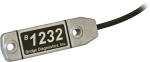
Not every sensor comes with a calibration sheet. If a calibration sheet is included, it is listed in the “Ships With” section of the sensor’s product web page or it is specified when ordered.
-
Sometimes, an old cable can be replaced with a new, shorter cable.
Sometimes, an existing cable can be shortened by cutting the ends off. However, there are a few issues that could be encountered when doing this:
- Some sensors have bridge completion resistors at the pigtail end.
- Some sensors are calibrated to length.
- Sometimes the color in the insulation may not be the same as that visible at the pigtail end.
Because of the potential issues, do not cut the ends off any sensor cable without first contacting Campbell Scientific to discuss the sensor in detail.
-
Whenever possible, purchase a sensor with the desired cable length. Some sensors have a user-specified cable length, whereas other sensors have a set cable length.
Sometimes, an old cable can be replaced with a new, longer cable.
Generally, additional cable cannot be spliced onto the existing cable because:
- Some sensor cables have bridge completion resistors at the pigtail end
- Some sensors are calibrated based on cable length
- Sometimes the color in the insulation is not the same as that visible at the pigtail end
- It is possible to introduce errors or malfunctions depending on the integrity of the splice
Splicing cable together increases the likelihood that water may enter the cable and cause shorting, corrosion, and some other potential issues, which in turn can cause measurement issues.
Because of the potential issues, do not splice any sensor cable without first contacting Campbell Scientific to discuss the sensor in detail.
-
Most Campbell Scientific sensors are available as an –L, which indicates a user-specified cable length. If a sensor is listed as an –LX model (where “X” is some other character), that sensor’s cable has a user-specified length, but it terminates with a specific connector for a unique system:
- An –LC model has a user-specified cable length for connection to an ET107, CS110, or retired Metdata1.
- An –LQ model has a user-specified cable length for connection to a RAWS-P weather station.
If a sensor does not have an –L or other –LX designation after the main model number, the sensor has a set cable length. The cable length is listed at the end of the Description field in the product’s Ordering information. For example, the 034B-ET model has a description of “Met One Wind Set for ET Station, 67 inch Cable.” Products with a set cable length terminate, as a default, with pigtails.
If a cable terminates with a special connector for a unique system, the end of the model number designates which system. For example, the 034B-ET model designates the sensor as a 034B for an ET107 system.
- –ET models terminate with the connector for an ET107 weather station.
- –ETM models terminate with the connector for an ET107 weather station, but they also include a special system mounting, which is often convenient when purchasing a replacement part.
- –QD models terminate with the connector for a RAWS-F Quick Deployment Station.
- –PW models terminate with the connector for a PWENC or pre-wired system.
-
Not every sensor has different cable termination options. The options available for a particular sensor can be checked by looking in two places in the Ordering information area of the sensor product page:
- Model number
- Cable Termination Options list
If a sensor is offered in an –ET, –ETM, –LC, –LQ, or –QD version, that option’s availability is reflected in the sensor model number. For example, the 034B is offered as the 034B-ET, 034B-ETM, 034B-LC, 034B-LQ, and 034B-QD.
All of the other cable termination options, if available, are listed on the Ordering information area of the sensor product page under “Cable Termination Options.” For example, the 034B-L Wind Set is offered with the –CWS, –PT, and –PW options, as shown in the Ordering information area of the 034B-L product page.
Note: As newer products are added to our inventory, typically, we will list multiple cable termination options under a single sensor model rather than creating multiple model numbers. For example, the HC2S3-L has a –C cable termination option for connecting it to a CS110 instead of offering an HC2S3-LC model.
-
Many times, but not always, a sensor’s cable can be replaced with a new cable. This is helpful if the original cable was damaged or if its length needs to be changed.
If the cable is attached to the sensor using a connector, Campbell Scientific will sell a replacement cable. For example, a 05106CBL-L is a replacement cable for a 05106-L. Replacement cables are listed in the “Replacement Parts” section of the Ordering information area of the product page.
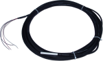
If the cable is attached to a sensor through a user-accessible terminal block, a raw cable can be purchased to replace it. For example, to replace the cable on a 05103-L Wind Monitor, order the desired length of pn 9721, 24 AWG 3 Twisted Pair Shielded Santoprene Cable. As another example, the raw cable for a TE525-L Rain Gage is pn 9661, 22 AWG 1 Twisted Pair Shielded Santoprene Cable.
If the cable is an integral part of the sensor, the cable cannot be user replaced, and the sensor must be returned to Campbell Scientific. Some examples of sensors that fall into this category include the 107-L, 109SS-L, 229-L, CS547A-L, and CS650-L. For the process of returning equipment to Campbell Scientific, refer to the Repair and Calibration page.
-
Many Campbell Scientific sensors are available with different cable termination options. These options include the following:
- The –PT (–PT w/Tinned Wires) option is the default option and does not display on the product line as the other options do. The cable terminates in pigtails that connect directly to a data logger.
- In the –C (–C w/ET/CS110 Connector) option, the cable terminates in a connector that attaches to a CS110 Electric Field Meter or an ET-series weather station.
- In the –CWS (–CWS w/CWS900 Connector) option, the cable terminates in a connector that attaches to a CWS900-series interface. Connection to a CWS900-series interface allows the sensor to be used in a wireless sensor network.
- In the –PW (–PW w/Pre-Wire Connector) option, the cable terminates in a connector that attaches to a prewired enclosure.
- In the –RQ (–RQ w/RAWS Connector) option, the cable terminates in a connector that attaches to a RAWS-P Permanent Remote Automated Weather Station.
Note: The availability of cable termination options varies by sensor. For example, sensors may have none, two, or several options to choose from. If a desired option is not listed for a specific sensor, contact Campbell Scientific for assistance.