
Self-calibrating; ideal for energy-balance in eddy-covariance and Bowen-ratio systems


Overview
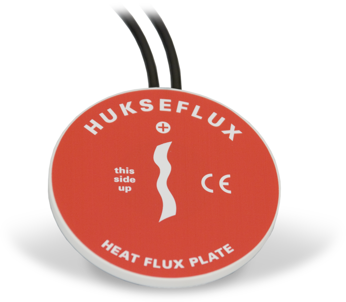
The HFP01SC, manufactured by Hukseflux, measures soil heat flux—typically for energy-balance or Bowen-ratio flux systems. It is intended for applications requiring the highest possible degree of measurement accuracy. The HFP01SC outputs a voltage signal that is proportional to the heat flux of the surrounding medium. At least two sensors are required for each site to provide spatial averaging. Sites with heterogeneous media may require additional sensors.
Read MoreBenefits and Features
- Corrects for errors due to differences in thermal conductivity between the sensor and surrounding medium, temperature variations, and slight sensor instabilities
- Compatible with most Campbell Scientific data loggers
- Uses Van den Bos-Hoeksma self-calibration method to provide a high degree of measurement accuracy
Images

Similar Products
Detailed Description
The HFP01SC consists of a thermopile and a film heater. The thermopile measures temperature gradients across the plate. During the in-situ field calibration, the film heater is used to generate a heat flux through the plate. The amount of power used to generate the calibration heat flux is measured by the data logger. Each plate is individually calibrated, at the factory, to output flux.
Self-calibration corrects for errors due to differences in thermal conductivity between the sensor and surrounding medium, temperature variations, and slight sensor instabilities.
Note: In an energy-balance installation, all sensors must be completely inserted into the soil face before the hole is backfilled.
Specifications
| Sensor Type | Thermopile with film heater |
| Sensitivity | 50 μV W-1 m-2 (nominal) |
| Nominal Resistance | 2 Ω |
| Temperature Range | -30° to +70°C |
| Expected Typical Accuracy | ±3% of reading |
| Heater Resistance | 100 Ω (nominal) |
| Heater Voltage Input | 9 to 15 Vdc |
| Heater Voltage Output | 0 to 2 Vdc |
| Duration of Calibration | ±3 minutes @ 1.5 W (typically performed every 3 to 6 hours) |
| Average Power Consumption | 0.02 to 0.04 W |
| Plate Diameter | 80 mm (3.15 in.) |
| Plate Thickness | 5 mm (0.20 in.) |
| Weight | 200 g (7.05 oz) without cable |
Related Documents
Product Brochures
Downloads
CR1000X HFP01SC Example program v.2 (3 kb) 18-02-2020
CR1000X program that measures the HFP01SC, performs the self-calibration, and checks for calibration validity. Refer to the manual for the equations used for the self-calibration and calibration-validity checks. A table in the manual provides a cross reference of the terms in the equations in the manual with the constants and variables in the example data logger program.
FAQs for
Number of FAQs related to HFP01SC-L: 13
Expand AllCollapse All
-
The example CRBasic program runs in either SequentialMode or PipeLineMode. To force the CRBasic program to run in PipeLineMode, add the instruction PipeLineMode to the beginning of the program.
-
Can the HFP01SC-L be embedded in railroad ballast, which comprises a blend of coarse rock particles?
No. The HFP01SC-L must be in full contact with the media. Railroad ballast is too coarse.
-
Rather than using a running average to find the millivolt output during a calibration, use a single sample with 50 or 60 Hz integration. See Example 1 in the 2014 or later version of the HFP01SC-L manual.
-
A calibration shift occurs if the HFP01SC-L is not making full contact with the soil during the calibration cycle. The following could cause the plate to lose contact with the soil: a soil freeze/thaw cycle, soil swelling/contracting because of extreme drying/wetting cycles, or rodents burrowing past the plate.
-
The in-situ calibration is helpful for quality assurance/quality control. The multiplier determined from the in-situ calibration should be within ±10% of the factory-determined calibration. If it is not, the plate may be damaged, not wired correctly to the data logger, or not making full contact with the soil.
-
The information included on a calibration sheet differs with each sensor. For some sensors, the sheet contains coefficients necessary to program a data logger. For other sensors, the calibration sheet is a pass/fail report.
-
Most Campbell Scientific sensors are available as an –L, which indicates a user-specified cable length. If a sensor is listed as an –LX model (where “X” is some other character), that sensor’s cable has a user-specified length, but it terminates with a specific connector for a unique system:
- An –LC model has a user-specified cable length for connection to an ET107, CS110, or retired Metdata1.
- An –LQ model has a user-specified cable length for connection to a RAWS-P weather station.
If a sensor does not have an –L or other –LX designation after the main model number, the sensor has a set cable length. The cable length is listed at the end of the Description field in the product’s Ordering information. For example, the 034B-ET model has a description of “Met One Wind Set for ET Station, 67 inch Cable.” Products with a set cable length terminate, as a default, with pigtails.
If a cable terminates with a special connector for a unique system, the end of the model number designates which system. For example, the 034B-ET model designates the sensor as a 034B for an ET107 system.
- –ET models terminate with the connector for an ET107 weather station.
- –ETM models terminate with the connector for an ET107 weather station, but they also include a special system mounting, which is often convenient when purchasing a replacement part.
- –QD models terminate with the connector for a RAWS-F Quick Deployment Station.
- –PW models terminate with the connector for a PWENC or pre-wired system.
-
Not every sensor has different cable termination options. The options available for a particular sensor can be checked by looking in two places in the Ordering information area of the sensor product page:
- Model number
- Cable Termination Options list
If a sensor is offered in an –ET, –ETM, –LC, –LQ, or –QD version, that option’s availability is reflected in the sensor model number. For example, the 034B is offered as the 034B-ET, 034B-ETM, 034B-LC, 034B-LQ, and 034B-QD.
All of the other cable termination options, if available, are listed on the Ordering information area of the sensor product page under “Cable Termination Options.” For example, the 034B-L Wind Set is offered with the –CWS, –PT, and –PW options, as shown in the Ordering information area of the 034B-L product page.
Note: As newer products are added to our inventory, typically, we will list multiple cable termination options under a single sensor model rather than creating multiple model numbers. For example, the HC2S3-L has a –C cable termination option for connecting it to a CS110 instead of offering an HC2S3-LC model.
-
This depends on the information contained in the calibration sheet:
- If the calibration sheet contains coefficient information, Campbell Scientific keeps a copy, and a replacement copy can be requested.
- If the calibration sheet does not contain coefficients, Campbell Scientific does not keep a copy. It may be possible to contact the original manufacturer for a replacement copy.